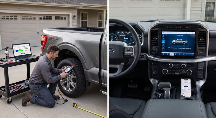
When I loaded a heavy bed of gravel into my F150 last fall, the dashboard scale display stayed completely frozen at zero.
I felt stressed thinking I had destroyed my height position sensors or faced a huge repair bill at the dealership.
Fortunately, learning the step-by-step ford f150 onboard scales calibration process fixed my sensor baseline instantly, and our team at Bryan’s Garage is here to show you how to zero your system easily.
Ford F150 Onboard Scales Calibration: Step-by-Step Guide
In This Article
Step-by-Step Calibration Procedures: Complete manual zeroing and FORScan sensor reset instructions for your Ford F150.
Chassis Height Sensor Mechanics: How leaf spring displacement and ride height sensors generate live payload readings.
Smart Hitch & Tongue Weight Management: How to balance trailer weight ratios and read smart taillight visual indicators.
Suspension Modification Adjustments: How leveling kits, lift blocks, and air bags alter scale accuracy and how to fix them.
🔴 MOST OWNERS NEVER FIND THIS
Your F-150 has a secret slot that starts the truck when your key fob dies. And 8 other things Ford never told you.
Dead fob fix · Remote window trick · 7.2 kW generator hiding in your bed · Tailgate ladder · and 5 more.
Connect your OBD2 diagnostic adapter firmly into the vehicle diagnostic port under the driver dashboard.
Plug the USB cable into your laptop and open the FORScan diagnostic software program.
Turn the vehicle ignition switch to the ON position without starting the engine.
Establish a connection in FORScan and navigate to the Service Functions tab.
Select the VDM (Vehicle Dynamics Module) or VMM module from the service list.
Execute the routine titled Ride Height Sensor Zero Position Calibration.
Follow the on-screen prompts while keeping the truck completely still and empty during the electronic command execution.
The computer will record new baseline voltage signals from all four suspension corner position sensors.
Step 6: Real-World Test and Weight Accuracy Verification.
Step 6:
Place a known weight into the center of the bed floor to test measurement calibration.
You can use two 50-pound bags of concrete or a known 100-pound barbell set for accurate testing.
Check the Sync 4 touchscreen scale display to confirm it registers the added test weight accurately within 5 percent.
Verify that the smart taillights illuminate the corresponding bottom LED bar as weight increases.
Remove the test weight from the bed and confirm the reading returns cleanly to zero pounds.If the reading returns to zero, your ford f150 onboard scales calibration process is completely successful.
Completing this maintenance process at home restores exact payload calculations without paying expensive dealership diagnostic labor rates.
🔧 Hidden F-150 Features — Confirmed by real owners
How Ford F150 Onboard Scales and Position Sensors Work Mechanically
Modern f150 onboard scales do not use traditional hydraulic load cells or physical bed strain gauges.
Instead, Ford engineers utilize rotary mechanical position sensors attached directly between the vehicle frame and suspension control arms.
These position sensors monitor real-time mechanical distance changes created when heavy cargo compresses the rear leaf springs.
Understanding this mechanical link explains why physical suspension changes alter scale calculations so drastically.
Mechanic Insight: The suspension position sensors measure mechanical deflection in millimeters. The computer uses programmed spring-rate math algorithms inside the Vehicle Dynamics Module to translate physical suspension sag into digital payload weight numbers.
When you place heavy tools, lumber, or gravel into the truck bed, gravity forces the frame lower toward the rear axle.
As the frame descends, the plastic linkage rods rotate the internal wiper arms inside the chassis position sensors.
The sensor converts mechanical arm rotation into a variable electrical voltage signal sent directly to the chassis control computer.
The Vehicle Dynamics Module continuously compares this live voltage signal against the stored factory zero-weight voltage baseline.
By processing spring compression distance alongside vehicle curb weight specifications, the computer calculates live payload weight in real time.
Because the system calculates weight based strictly on suspension sag distance, anything that alters ride height affects reading accuracy.
System Component
Mechanical Function
Impact on Scale Accuracy
Common Failure Mode
Height Position Sensor
Measures vertical frame deflection angle
Direct primary signal source for weight calculation
Software calibration drift after battery disconnect
Smart LED Taillights
Displays vertical visual weight indicators
Provides outside visual feedback during bed loading
Corroded wiring harness pins or blown fuses
The computer updates payload calculations dozens of times per second while the truck remains parked during loading operations.
When the vehicle accelerates above 5 miles per hour, the computer locks the scale display to prevent road bumps from causing false readings.
If your leaf springs wear out and sag over time, the computer interprets permanent leaf spring sag as permanent bed cargo.
Performing a ford f150 onboard scales reset rewrites the baseline voltage tables inside the VDM module to accommodate suspension aging.
This intelligent software compensation keeps your real-time bed measurements accurate across the entire operating life of your truck.
Calculating Payload, Smart Hitch Tongue Weight, and Trim Compatibility
Ford F150 Onboard Scales Calibration: Step-by-Step Guide
The Ford smart scale package provides crucial safety advantages for truck owners who haul work materials or tow heavy trailers daily.
Exceeding your truck Gross Vehicle Weight Rating creates severe brake fade, tire overheating, and frame stress hazards.
The onboard scale system monitors two distinct weight metrics: bed payload weight and trailer tongue weight through Smart Hitch technology.
Knowing your exact trim capability ensures you stay well within legal operating weight limits on the highway.
Key Safety Standard: Ideal trailer towing dynamics require 10 percent to 15 percent of the total trailer weight to rest directly on the hitch ball. Smart Hitch measures tongue weight instantly so you can adjust cargo placement inside the trailer before hitting the highway.
When you attach a travel trailer or utility trailer to your rear receiver, Smart Hitch calculates tongue weight force on the rear axle.
The Sync 4 screen guides you through entering your total estimated trailer weight into the system menu.
The screen display calculates whether your current tongue weight sits in the safe green zone or dangerous red zone.
If tongue weight is too low, the trailer will sway violently behind your truck at highway cruising speeds.
If tongue weight is too high, your front tires lose steering traction while blinding oncoming traffic with angled headlights.
Smart Hitch provides immediate visual guidance so you can shift heavy cargo forward or rearward inside the trailer bed.
F150 Trim Level
Scale System Availability
Smart Taillight Display
Primary Target Application
XL & XLT Trims
Optional in Towing Tech Packages
Optional based on lighting trim
Fleet work, light hauling, DIY utility towing
Lariat & Tremor
Standard on High Equipment Groups
Standard full 4-bar LED display
Overlanding, heavy payload hauling, camper towing
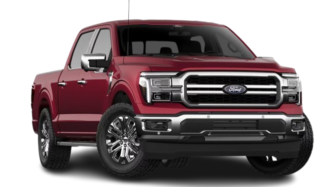
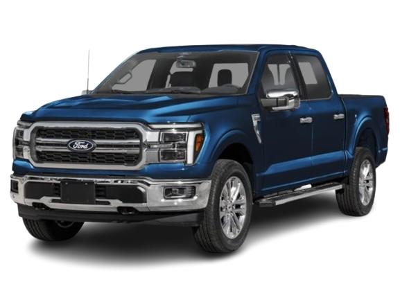
King Ranch & Platinum
Standard Equipment
Standard full 4-bar LED display
Luxury daily driving, heavy enclosed trailer towing
Raptor & Raptor R
Available depending on option packages
Integrated with Fox Live Valve sensors
High-speed off-roading and specialized desert payload
The smart taillight system provides brilliant real-world convenience while loading cargo in remote work locations.
Four vertical LED bars built inside the rear tail lamps illuminate sequentially as bed weight increases toward maximum payload capacity.
One bar indicates 25 percent capacity, two bars indicate 50 percent, three bars indicate 75 percent, and four bars indicate 100 percent capacity.
If you accidentally overload the bed past maximum ratings, the top LED bar flashes continuously to warn you to stop loading.
This visual feedback allows excavator operators and forklift drivers to load your bed safely without guessing payload weight.
Practical Application Guide and Post-Install Optimization
Applying aftermarket modifications like rear levelling blocks, air helper springs, or heavy bumpers alters physical scale calculations immediately.
Whenever you change physical suspension geometry, you must follow specific recalibration steps to maintain system functionality.
Step 1: Adjusting Sensor Linkage Arms After Installing Suspension Lifts.
Installing a rear lift block raises the frame away from the rear axle housing permanently.
This mechanical gap over-extends the plastic height sensor linkage arms into an artificial full-droop position.
The computer interprets this extreme angle as an empty bed or invalid sensor fault code.
Install bolt-on sensor extension brackets to drop the upper sensor pivot mount down by the exact thickness of your lift block.
Verify that the sensor linkage arm returns to a horizontal parallel position relative to the frame rail.
Step 2: Recalibrating Scales After Adding Air Helper Springs.
Air bags prevent rear leaf springs from sagging under heavy tongue weights and bed loads.
Because onboard scales rely on physical spring compression distance to measure weight, air bags confuse the system.
When you inflate air bags to 50 PSI, the suspension stays high even under a 1,000-pound bed load.
The onboard scale system will read near zero pounds because the height sensors do not detect physical frame descent.
To use scales accurately with air bags, deflate air bags to 5 PSI baseline pressure while reading payload weight.
Once you verify payload weight on the screen, inflate air bags to level out your driving ride height.
Step 3: Setting Up Custom Accessory Tare Weights in Sync 4.
Installing a heavy steel bed topper, sliding tool drawer, or commercial ladder rack adds permanent tare weight.
A heavy fiberglass topper adding 200 pounds reduces your available maximum payload rating by 200 pounds instantly.
Open your Sync 4 Onboard Scales menu with the new accessories installed on your truck.
Press the Set New Baseline Tare button on the touchscreen display.
The computer saves the new accessory weight as your permanent zero baseline, ensuring future cargo readings remain 100 percent accurate.
Taking time to adjust sensor mounts and set custom accessory baselines keeps your smart features operating flawlessly.
If you ever run into stubborn electronic faults, our expert troubleshooting guides at Bryan’s Garage provide step-by-step solutions.
Overcoming Risks and Common DIY Maintenance Mistakes
Ford F150 Onboard Scales Calibration: Step-by-Step Guide
Working around sensitive chassis sensors requires careful handling to prevent costly mechanical component damage.
Understanding potential DIY mistakes ensures your calibration project goes smoothly without triggering hidden dashboard trouble lights.
Critical Precaution: Never force or bend plastic height position sensor linkage arms by hand. Plastic ball sockets snap easily when twisted past their intended rotational limits, requiring complete sensor replacement.
A common mistake home mechanics make is calibrating the system on an uneven or sloped driveway surface.
If the truck sits on a steep slope, weight shifts toward the rear axle, causing sensors to misread side-to-side chassis balance.
Calibrating on a slope programs permanent weight errors into memory, causing incorrect readings during normal driving.
Always verify that your floor surface sits completely level before executing screen zeroing or FORScan software routines.
Another frequent error involves ignoring broken or dirty electrical connectors located behind the rear wheels.
Road salt, mud, and pressure washer spray penetrate sensor wiring harnesses over time, causing corroded connector pins.
Corroded pins create intermittent voltage drops that freeze dashboard weight readings or trigger yellow wrench warning lights.
Disconnect sensor harness plugs annually and clean internal pins thoroughly using electrical contact cleaner and dielectric grease.
Avoiding these common pitfalls protects your expensive smart features and guarantees years of reliable payload monitoring.
🟢 Going viral on F150Forum & Reddit
“I’ve driven an F-150 for 4 years and didn’t know this existed.” — The most common reaction when this article is shared
9
features
2015+
models
11 min
read
Free
no signup
Did you know which button on your fob opens the tailgate when your hands are full? Or the button combo to reset CarPlay in 15 seconds without turning off the engine?
Is it safe to perform an onboard scale calibration at home?
Yes, calibrating your onboard scales using the Sync 4 touchscreen or FORScan software is completely safe to perform at home.
The calibration software only rewrites sensor baseline tables and does not alter critical engine or braking safety parameters.
How much does it cost to calibrate onboard scales at a Ford dealership?
Dealership service departments typically charge between $150 and $250 in diagnostic labor fees to perform a ride height sensor reset.
Performing the screen tare reset yourself costs zero dollars, while a FORScan OBD2 adapter costs roughly $35 online.
What tools do I need to reset my onboard scales after a leveling kit?
You need a flat level concrete driveway, a tape measure, sensor drop brackets, and a laptop with an OBD2 interface cable running FORScan.
If you only need to reset daily cargo weight, no mechanical tools are required beyond the Sync 4 touchscreen menu.
How long does the complete recalibration process take?
A simple Sync 4 touchscreen zero reset takes less than two minutes from start to finish.
A full electronic FORScan ride height sensor calibration after installing suspension lifts takes approximately 20 to 30 minutes.
Why does my onboard scale display a red error icon on the screen?
A red scale error icon indicates a disconnected height sensor, broken linkage arm, or severe suspension over-extension conflict.
Inspect under the rear wheel arches to confirm all plastic sensor linkage arms remain securely connected to their mounting ball studs.
Conclusion
Calibrating your F150 smart scales restores accurate payload monitoring, protects your suspension, and ensures safer trailer towing.
Following proper sensor setup steps gives you total confidence when hauling heavy work cargo or setting up campers.
Ready to transform your car maintenance from a stressful chore into a breeze? Explore more tips at Bryan’s Garage.
Have questions? Our team can help you find the best solutions for your car problems and avoid costly mechanic visits.
Note: Individual results may vary depending on individual vehicle makes, models, year of manufacture, and overall condition. This article is intended for general automotive reference purposes only and does not replace official manufacturer service manuals or advice from a certified mechanic.