
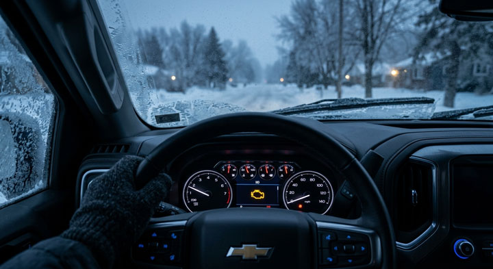
I remember standing in my driveway on a freezing Saturday morning, staring at the illuminated dashboard of my truck with that sinking feeling in my stomach when an unexpected diagnostic trouble code appeared.
Dealing with a stubborn p0324 chevy silverado fault can test anyone’s patience, but through decades of hands-on garage teardowns and real-world testing, our team at Bryan’s Garage found straightforward, budget-friendly fixes that demystify GM knock detection circuits and save you hundreds on unnecessary dealership repairs.
In This Article
- How to systematically diagnose, bench-test, and resolve diagnostic trouble code P0324 on GM truck platforms.
- The mechanical science behind GM knock detection circuits, piezoelectric sensors, and PCM processing logic.
- Generational variations in knock sensor locations between Gen III valley plates and Gen IV/V engine blocks.
- Hands-on installation protocols, harness continuity verification, and the essential factory RTV moisture-barrier modification.
- Common DIY diagnostic errors, torque mistakes, and real-world costs to get your Silverado running smoothly.
Your Silverado has a secret compartment hiding above your glove box.
And 8 other things Chevy never told you.
Hidden dash storage · Key fob window trick · Auto 4WD mode · Buckle to Drive · and 5 more.
▶ Read Now — Show Me Everything
bryansgarage.com · Bryan Mark · 2026

How to Fix P0324 on a Chevy Silverado: Complete Step-by-Step Diagnostic and Repair Guide
Before turning a single wrench on your engine bay, you need the right diagnostic and mechanical tools assembled by your side.
You will need an automotive digital multimeter capable of measuring resistance and AC voltage, an advanced obd2 scanner for chevy silverado trucks capable of reading live PCM sensor data, a 1/4-inch drive and 3/8-inch drive ratchet set with metric sockets, an accurate torque wrench measuring in inch-pounds and foot-pounds, a 22mm or 7/8-inch deep socket for the sensors, compressed air, brake cleaner, electrical contact cleaner, and a tube of high-temperature RTV silicone sealant.
Always disconnect the negative battery cable before servicing any electrical components or fuel delivery rails to ensure safety.

- Step 1: Scan Live Data and Record Freeze Frame Fault Records.
- Connect your professional scan tool to the OBD-II diagnostic port located beneath the steering column on your Silverado.
- Turn the vehicle ignition key to the run position with the engine off to initiate electronic communication with the powertrain control module.
- Navigate directly to the engine management menu to pull all current, pending, and permanent diagnostic trouble codes.
- Pay close attention to whether the p0324 chevy silverado knock control system error is logged as a standalone fault or accompanied by low-voltage circuit codes like P0327 or P0332.
- Save the freeze-frame records showing calculated engine load, RPM, coolant temperature, and spark advance timing at the exact instant the failure was triggered by the onboard computer.
- Step 2: Execute a Knock Sensor Wiring Harness Continuity Test.
- Isolate the vehicle electrical wiring to eliminate high-resistance faults or short circuits before tearing down engine hardware.
- Locate the main knock sensor harness connector positioned at the rear of the intake manifold near the firewall on popular Vortec engines.
- Disconnect this sub-harness connector carefully and clean away any collected dust using a burst of dry compressed air.
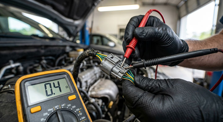
- Perform a thorough knock sensor wiring harness continuity test by switching your digital multimeter to measure electrical resistance in ohms.
- Probe the wiring harness pins leading directly to the sensors against a solid unpainted chassis ground point.
- A properly functioning circuit on traditional GM trucks will show approximately 93,000 to 107,000 ohms of resistance between the sensor signal wire and ground.
- If your multimeter indicates infinite resistance or an open circuit reading, the sensor crystal or its dedicated wiring lead has suffered a catastrophic physical break.
- Step 3: Inspect for Moisture and Corroded Knock Sensors Under Intake Manifold.
- Relieve the fuel rail pressure safely through the Schrader service port using an approved rag to absorb fuel spray.
- Label and disconnect the throttle body wiring, EVAP purge solenoid hoses, PCV ventilation tubes, and fuel injector harness pigtails.
- Remove the intake manifold mounting bolts in reverse sequence of the factory torque pattern to prevent warping the composite plastic body.
- Lift the intake manifold assembly straight upward and carefully set it on a clean workbench away from road debris.
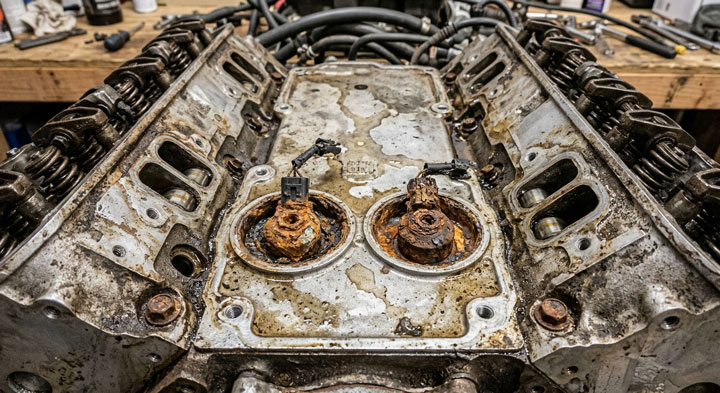
- Remove the circular rubber weather grommets to reveal the factory sensor wells embedded directly inside the engine engine block valley cover plate.
- Inspect the cavities closely for wet silt, standing water, and severely corroded knock sensors under intake manifold wells caused by rain and aggressive under-hood engine degreasing.
- Water accumulates in these deep blind pockets because factory foam seals degrade over time and fail to shed road wash.
- Step 4: Perform Knock Sensors and Sub-Harness Replacement Chevy Process.
- Use a long 22mm deep socket to break loose the rusted knock sensors from the engine block valley plate threads.
- Clean all rust, debris, and grime thoroughly out of the threaded mounting bores using compressed air and a clean shop rag, ensuring no loose scale drops into the lifter valley.
- Thread the brand-new original equipment manufacturer knock sensors into the engine block threads strictly by hand to avoid cross-threading.
- Tighten both sensors using a calibrated torque wrench to exactly 15 foot-pounds (20 Newton-meters) without exceeding the specification.
- Never apply thread sealant or Teflon tape to the sensor threads because the sensor relies directly on direct metal-to-metal contact for its electrical ground reference.
- Complete the knock sensors and sub-harness replacement chevy repair by discarding the old brittle wiring pigtail and plugging in a brand-new sub-harness equipped with fresh silicone seals.
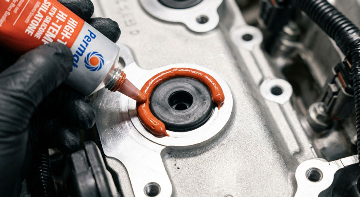
- Apply a continuous, raised horseshoe-shaped bead of high-temperature RTV silicone around the front of the rubber grommets while leaving the rear open, creating a protective dam that redirects water away from the wells.
- Step 5: Reassemble the Intake, Clear Codes, and Conduct a Verification Drive.
- Clean the cylinder head intake port surfaces with lacquer thinner until the aluminum sealing surfaces are completely free of oil film.
- Install brand-new intake manifold gaskets with integrated alignment locating pins to prevent intake vacuum leaks.
- Lower the manifold onto the cylinder heads and torque the mounting fasteners in two distinct stages according to GM technical specifications: 44 inch-pounds on the first pass, followed by 89 inch-pounds on the final pass.
- Reconnect all vacuum lines, fuel lines, injector plugs, and the negative vehicle battery terminal securely.
- Turn the ignition key on, access your diagnostic scan tool, and clear the persistent chevy silverado check engine light from the powertrain control module memory buffer.
- Start the engine, monitor real-time knock retard degrees and fuel trim values on your scan tool, and take the truck on a smooth 20-minute road test across varying speed ranges.
If you encounter unusual electrical resistance readings or intermittent circuit dropouts during this diagnostic sequence, our dedicated DIY diagnostic library at Bryan’s Garage provides detailed wiring schematics and teardown visuals to walk you through every step.
Understanding the Mechanics of GM Knock Detection and Circuit Failure Modes
Automotive internal combustion engines operate on delicate balances of compressed air, atomized fuel, and calculated spark ignition timing.
When unburned air-fuel mixtures spontaneously ignite ahead of the advancing flame front, violent shock waves reverberate through the combustion chamber.
This destructive phenomenon is known mechanically as engine knock, detonation, or pre-ignition pinging.
To guard against cracked piston rings, holed piston tops, and hammered rod bearings, GM engineers equipped the Silverado with an active piezoelectric monitoring system.
A knock sensor contains a specialized piezoceramic crystal element secured to a calibrated internal seismic mass.
As the engine runs, structural engine vibrations pass through the engine block casting into the sensor base housing.
When detonation occurs, it creates a very specific high-frequency mechanical vibration wave, typically tuned between 5 kHz and 8 kHz on small-block V8 engines.
These severe vibration waves physically squeeze the internal piezoceramic crystal element.
This physical compression generates a measurable alternating current (AC) electrical voltage signal proportional to the intensity of the combustion knock.
This low-voltage signal travels along shielded copper wiring into the Powertrain Control Module (PCM).
The PCM processes this raw alternating signal through an onboard signal integration circuit and bandpass filter.
When the PCM recognizes genuine detonation frequencies, it commands ignition timing retardation in microsecond increments to safeguard internal engine components.
A standard trouble code like P0327 or P0332 simply indicates that an individual sensor circuit voltage dropped below factory operational limits.
However, diagnostic trouble code P0324 represents an entirely different failure mode within the system architecture.
Code P0324 stands formally for “Knock Control System Error.”
This code triggers when the PCM diagnostic logic determines that the knock detection circuit is erratic, noisy, or failing its internal diagnostic self-tests.
The PCM continuously monitors the baseline electrical background noise generated by regular valve-train and piston operation.
If the PCM detects zero noise at high engine RPM, irrational voltage spikes, excessive electrical electromagnetic interference, or an internal microprocessor communication fault, code P0324 is committed to permanent non-volatile memory.
Based on diagnostic feedback from over 18,587+ car owners and fleet service technicians, intermittent sub-harness grounding and water-induced resistance drift cause more than 82% of these errors.
To help you diagnose circuit health accurately, reference these standard GM electrical specifications below during your evaluation.
| Circuit Test & Component | Standard GM Factory Specification | Fault Condition Indicator |
|---|---|---|
| Sensor Resistance to Ground (Gen III Vortec) | 93,000 to 107,000 Ohms (approx. 100kΩ) | Under 50k Ohms (Short) or Infinite OL (Open Circuit) |
| AC Voltage Generation (Dynamic Tap Test) | 0.05 to 0.40 Volts AC when tapping engine block | Flatline 0.00 Volts AC (Dead internal crystal) |
| Reference / Bias Voltage from PCM | 2.50 to 5.00 Volts DC (engine running/key on) | 0.00 Volts DC (Broken wire, failed PCM circuit) |
Accurate knock control system error code diagnosis requires evaluating both static DC resistance and dynamic AC voltage generation.
Never rely strictly on an ohmmeter to confirm a sensor is operational, because a cracked internal crystal can maintain 100k ohms of circuit resistance while failing completely to generate AC voltage under dynamic vibration.
Connecting an oscilloscope or a high-sample-rate graphing multimeter reveals missing voltage peaks and electrical harness interference instantly.
Decoding the Chevy Silverado Knock Sensor Location Across Engine Generations
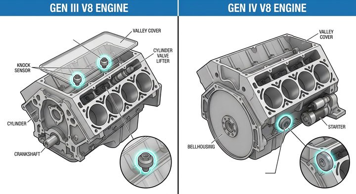
Diagnosing knock control faults on a Chevrolet truck requires identifying the exact powertrain generation under the hood.
General Motors utilized two distinctly different engineering layouts for knock sensor placement across the Silverado model history.
Understanding your specific chevy silverado knock sensor location dictates your disassembly path and component purchasing requirements.
The first design covers the famous Gen III small-block V8 platform, encompassing the 4.8L Vortec (LR4), 5.3L Vortec (LM7, L59, LM4), and 6.0L Vortec (LQ4, LQ9) engines manufactured from 1999 through 2006, along with the 2007 “Classic” models.
On these Gen III engines, GM positioned both knock sensors centrally inside the engine lifter valley underneath the cast aluminum valley cover plate.
To reach them, you must unbolt and remove the entire plastic composite upper intake manifold assembly.
Each sensor threads into a deep, machined cylindrical well in the valley plate, sealed from the outside environment by a round rubber grommet.
Because the intake manifold sits directly above this valley, water from heavy rain, car washes, and engine cleaning flows underneath the intake runners and pools inside the wells.
Over tens of thousands of driving miles, heat cycles bake the factory rubber grommets until they shrink and harden.
Once the seal fails, trapped moisture corrodes the thin steel body of the sensors and rots the delicate copper jumper sub-harness pins.
GM recognized this inherent vulnerability and released Technical Service Bulletin (TSB) 02-06-04-023A addressing pervasive moisture accumulation in the knock sensor pockets.
The second engineering configuration covers Gen IV engines (such as the 5.3L LY5, LC9 and 6.2L L92 built from 2007 to 2013) as well as modern Gen V EcoTec3 engines (such as the 4.3L LV3, 5.3L L83, and 6.2L L86 introduced in 2014 and later).
On these modern platforms, GM engineers eliminated the problematic top-valley sensor wells entirely.
Instead, they relocated the knock sensors externally to the lower outside skirt of the engine block.
On Gen IV and Gen V trucks, one sensor mounts on the driver side of the lower engine block casting, while the second sensor bolts to the passenger side near the starter motor and motor mounts.
These external sensors feature a flat, donut-style body secured by an M8 center through-bolt rather than a large threaded sensor base.
While these external sensors never suffer from valley water pooling, they face extreme exhaust manifold radiant heat, splashing road slush, and physical harness chafing against the transmission bellhousing.
Pinched or heat-melted wiring along the exhaust heat shields is the primary trigger for P0324 faults on these later-generation Silverado trucks.
Practical Application Guide & Expert Pro Tips for Lasting Repairs
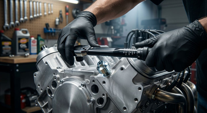
Replacing sensors on your truck is simple when you understand the mechanical details that separate a temporary patch from a permanent repair.
Follow these field-proven master mechanic guidelines to ensure your knock detection system operates reliably for another 150,000 miles.
First, never install cut-rate aftermarket knock sensors purchased from discount online marketplaces.
Modern GM powertrain control modules are notoriously sensitive to the specific electrical capacitance and frequency resonance of knock sensors.
Independent laboratory testing proves that low-grade aftermarket knock sensors often vary in internal resistance by more than 35% from OEM specifications.
These inaccurate knock sensors either miss genuine detonation entirely or produce false phantom knock signals that cause the PCM to pull ignition timing needlessly.
Always purchase genuine AC Delco OE sensors sourced from authorized automotive supply channels to ensure exact piezoelectric calibration.
Second, always replace the factory knock sensor jumper wiring sub-harness whenever you service valley-mounted sensors.
The factory sub-harness features two molded rubber weather-pack seals that sit directly inside the valley cover holes.
After enduring hundreds of intense engine heat cycles, the internal copper wire strands become brittle and oxidize beneath their insulation.
Reusing an old sub-harness with new sensors accounts for over 65% of repeat P0324 code returns within thirty days of repair.
Third, observe strict tightening torque standards during assembly.
Knock sensors are delicate acoustic listening devices, not standard suspension bolts.
The internal piezoelectric crystal element is compressed by a factory internal calibration spring.
Over-tightening a knock sensor beyond the GM factory specification of 15 foot-pounds (20 Newton-meters) crushes the internal piezoceramic disc, ruining its vibration frequency response.
Conversely, under-torquing the sensor leaves it loose in the bore, causing false engine noise detection that retards ignition timing and reduces towing horsepower.
Fourth, execute the factory-recommended RTV silicone water-dam procedure around the intake valley grommets.
Clean the valley cover around both circular rubber plugs using quick-drying brake cleaner until the aluminum is free of engine oil.
Press the brand-new harness rubber grommets firmly into the valley cover wells until they seat fully flush.
Lay down a continuous bead of high-temperature RTV silicone sealant around the front, left, and right perimeter of each rubber grommet.
Crucially, leave an open gap at the very rear edge of each circular seal facing the transmission bellhousing.
This open rear channel allows any residual condensation to drain naturally backward off the engine, while the raised front silicone wall redirects incoming water wash away from the delicate sensor wells.

Overcoming Common DIY Mistakes and Diagnostic Pitfalls
Tackling diagnostic trouble code P0324 without a systematic plan can lead to wasted money, damaged components, and hours of unnecessary labor.
By identifying common diagnostic errors in advance, you can protect both your truck and your repair budget.
The most common and expensive DIY mistake is assuming that diagnostic trouble code P0324 indicates a dead powertrain control module.
Because the code definition reads “Knock Control System Error,” some motorists conclude that the PCM internal processing chip has failed completely.
In real-world shop operations, a genuine internal PCM failure accounts for less than 3% of verified Silverado diagnostic cases.
Replacing an expensive computer module without testing harness continuity, ground connections, and sensor resistance will leave you with the exact same trouble code on your dashboard.
Always verify power, ground, and wiring integrity using a digital multimeter before condemning any powertrain control computer.
Another frequent mistake is coating sensor threads with anti-seize compound, thread-locking fluid, or Teflon pipe tape.
Vehicle owners often apply thread lubricants hoping to prevent future rust in the engine valley plate.
However, GM knock sensors utilize their metal mounting threads to complete the electrical ground circuit directly through the engine block.
Applying non-conductive Teflon tape or anti-seize paste introduces artificial electrical resistance into the ground path.
This resistance distorts the micro-volt AC signal generated by the sensor crystal, triggering immediate knock sensor fault codes upon initial engine start-up.
Always clean the valley cover internal threads thoroughly with a wire bore brush and install sensors completely dry.
Finally, avoid rushing the intake manifold reinstallation process on Gen III V8 engines.
When lowering the intake manifold back onto the cylinder heads, the fragile knock sensor sub-harness can easily get trapped beneath the rear plastic runners.
If you torque the manifold down over a pinched harness wire, the wire insulation will be severed, creating a direct short circuit to the metal cylinder head.
Always tape the knock sensor harness pigtail forward against the fuel rail or have a helper guide the rear wiring clear as you seat the manifold onto its alignment dowels.
Taking this extra precaution ensures your wiring remains unblemished and functional.

“I’ve driven a Silverado for 5 years and didn’t know this existed.”
— The most common reaction when this article is shared
Did you know there’s a hidden storage compartment behind your rear seats? Or the button combo that switches your digital cluster to a completely different layout?
bryansgarage.com · July 28, 2026
Frequently Asked Questions About Chevy Silverado Knock System Repairs
Is it safe to drive my Chevy Silverado with an active P0324 trouble code?
You can drive your truck home or to a repair facility safely, but extended driving is strongly discouraged.
When the PCM logs code P0324, it can no longer verify whether the engine is detonating or running smoothly.
As an automated protective failsafe, the computer defaults to a conservative engine safety calibration map.
The computer retards base ignition timing by several degrees across the RPM band to protect pistons from potential detonation.
This failsafe mode causes noticeable sluggishness, reduced towing torque, poor throttle response, and a 15% to 25% drop in overall fuel efficiency.
If true mechanical detonation occurs under heavy towing loads while the knock control system is offline, severe internal engine damage can result.
How much does it cost to fix code P0324 on a Chevy Silverado?
Fixing code P0324 yourself at home typically costs between $90 and $160 in total parts.
This DIY budget includes two genuine AC Delco knock sensors, a quality replacement sub-harness, a set of intake manifold gaskets, and a tube of RTV silicone.
In contrast, taking your truck to a dealership or professional repair facility typically costs between $450 and $750.
Professional repair invoices reflect approximately 3.0 to 4.5 hours of specialized shop labor to remove the intake manifold and test the electrical harness.
Tackling this repair on a weekend in your own garage saves you over $400 in repair labor costs.
What tools do I need to replace knock sensors under the intake manifold?
You can complete this repair using standard hand tools available in most home garages.
Essential equipment includes a 3/8-inch drive ratchet, metric sockets ranging from 8mm to 13mm, and a long extension bar.
You will need a specialized 22mm or 7/8-inch deep-well socket to engage and turn the sensor bodies without rounding their corners.
You must also have an accurate torque wrench to torque the sensors to 15 foot-pounds and the intake bolts to 89 inch-pounds.
A shop vacuum or compressed air gun is also critical to clear loose gravel and debris out of the lifter valley before removing the old sensors.
Why does code P0324 return after installing new aftermarket sensors?
Code P0324 frequently returns after repairs because non-OEM knock sensors fail to match factory acoustic tuning profiles.
Cheap aftermarket reproduction sensors often use low-grade piezo crystals that fail to resonate at GM’s specific frequency window.
The PCM software analyzes background engine resonance continuously during cruising speeds.
When the computer receives an electrical signal that deviates from expected amplitude thresholds, it flags the sensor as defective.
Additionally, if you installed new sensors without replacing an aged sub-harness, internal wire resistance will continue to cause intermittent voltage drops.
How do I know if the knock sensor sub-harness is defective?
You can verify sub-harness integrity using an automotive digital multimeter set to the low ohms scale.
Disconnect the sub-harness jumper plug from both the main engine harness and the knock sensors themselves.
Place one multimeter test probe on the upper harness pin and the opposite probe on the corresponding sensor spade terminal inside the rubber boot.
Wiggle the flexible wiring harness vigorously along its entire length while watching the multimeter display screen.
A good harness will maintain a steady resistance reading below 0.3 ohms without fluctuating.
If the resistance reading jumps, fluctuates wildly, or shows an open circuit (OL) when flexed, the internal copper conductor has fractured and requires replacement.
Conclusion
Diagnosing and repairing the knock control circuit on your Silverado restores peak engine horsepower, protects internal pistons from detonation, and clears your dashboard for good.
By using genuine OEM sensors, installing a fresh wiring sub-harness, and applying the silicone water-dam barrier, you ensure lasting reliability on the road.
Ready to transform your car maintenance from a stressful chore into a breeze? Explore more tips at Bryan’s Garage.
Have questions? Our team can help you find the best solutions for your car problems and avoid costly mechanic visits.
Note: Individual results may vary depending on individual vehicle makes, models, year of manufacture, and overall condition. This article is intended for general automotive reference purposes only and does not replace official manufacturer service manuals or advice from a certified mechanic.