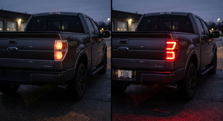
When I bought my project truck, I spent an entire rainy Saturday afternoon stranded in my driveway trying to figure out why my rear signal lights were rapid-flashing like crazy after a simple LED bulb swap.
I was staring at a bundle of faded factory wiring underneath my rear bumper, completely overwhelmed by conflicting pinout charts and terrified of blowing an expensive body control module.
That frustrating experience drove me to master electrical diagnostics and assemble this definitive ford f150 tail light wiring diagram guide.
Here at Bryan’s Garage, our master mechanics are excited to walk you step-by-step through decoding your truck’s rear harness, fixing annoying electrical glitches, and completing high-performance light upgrades safely.
In This Article
- Step-by-Step Electrical Guide: How to trace, test, splice, and upgrade rear lighting harnesses safely.
- Wire Color Code Charts: Comprehensive pinout tables covering multiple Ford F-150 model generations.
- Troubleshooting Hyperflash & BCM Trips: Resolving CANbus faults, load resistance requirements, and bad chassis grounds.
- LED & Tag Light Upgrades: Converting halogen housings to modern LED assemblies and license plate illuminators.
- Preventative Wiring Maintenance: Protecting factory harnesses from moisture intrusion, salt corrosion, and wire rubbing.
Your F-150 has a secret slot that starts the truck when your key fob dies.
And 8 other things Ford never told you.
Dead fob fix · Remote window trick · 7.2 kW generator hiding in your bed · Tailgate ladder · and 5 more.
▶ Read Now — Show Me Everything
bryansgarage.com · Bryan Mark · 2026

How to Trace and Upgrade Your Ford F150 Tail Light Wiring: A Complete Step-by-Step Guide
Understanding rear lighting circuitry on your Ford truck is essential for both simple maintenance and custom upgrades.
Whether you are replacing broken halogen housings, wiring a trailer hitch accessory, or converting to modern LED lamps, working systematically prevents blown fuses.
Modern Ford trucks utilize sophisticated multiplexed lighting systems controlled directly by the Body Control Module (BCM).
Following a precise testing and wiring process guarantees your turn signals, brake lights, and reverse lamps function flawlessly without triggering dash warnings.
Prerequisites & Required Tools
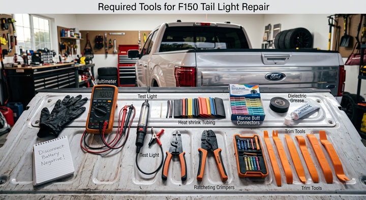
Before disconnecting any factory electrical connectors under the bed, prepare your diagnostic tools and safety equipment.
Working on live automotive circuits requires accurate testing tools to prevent short circuits.
You will need a digital multimeter capable of measuring DC voltage and continuity ohms.
Prepare an automotive 12V test light, wire strippers, ratcheting crimping pliers, and non-conductive nylon trim tools.
Gather heat shrink tubing, marine-grade heat shrink butt connectors, electrical tape, and dielectric grease.
Disconnecting the negative terminal of your truck battery prior to cutting wires prevents accidental circuit grounds.
Step 1: Accessing the Rear Light Housings and Factory Harness
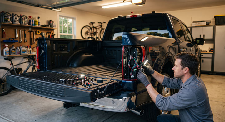
Lower your Ford F-150 tailgate down completely to gain access to the inner bed pillar bolts.
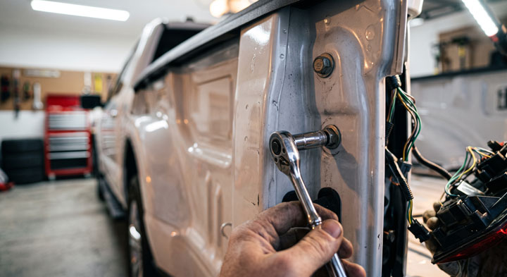
Locate the two 8mm mounting bolts holding the tail light assembly against the inner bed wall.
Remove both bolts using an 8mm socket and ratchet set.
Grasp the outer lens housing firmly with both hands and pull straight back toward the rear bumper.
Avoid pulling the housing sideways, as this can snap the plastic alignment pins molded into the bed sheet metal.
Locate the primary wiring harness connector plugged into the back of the light housing assembly.
Press down firmly on the plastic locking tab and slide the connector plug out from the socket.
Inspect the connector pins inside for green copper corrosion or bent metal terminals.
Step 2: Identifying Pinouts and Wire Color Functions
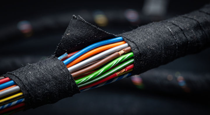
Expose three inches of the rear wiring harness by carefully peeling back the protective black cloth tape.
Examine the individual insulated wires leading to the stop, turn, parking, and reverse bulb sockets.
Locate the primary ground wire, which is solid black or black with a yellow tracer stripe across most model years.
Identify the running light circuit wire, which feeds constant twelve-volt power whenever your headlight switch is turned on.
Identify the dedicated turn signal and brake light feed wires for both driver and passenger sides.
On most Ford trucks, the driver side and passenger side turn signal circuits utilize distinct wire tracer colors to separate signal channels.
Step 3: Testing Voltage and Ground Continuity with a Multimeter
Reconnect your truck’s negative battery cable to perform live voltage verification tests.
Set your digital multimeter dial to DC Volts on the 20-volt scale setting.
Connect the black multimeter probe directly to a clean, unpainted steel frame bolt or rear bumper ground point.
Turn on your truck’s parking lights from the driver cab light switch knob.
Touch the red multimeter probe into the harness connector pin feeding the parking light circuit.
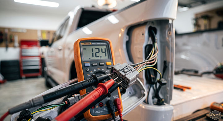
Verify that your multimeter displays between 12.2 and 12.8 volts DC.
Switch your multimeter to resistance ohms mode and test continuity between the harness ground pin and the frame chassis.
A reading below 0.5 ohms confirms a healthy, low-resistance ground connection that will support stable lighting performance.
Step 4: Installing Load Resistors for LED Hyperflash Prevention
If you are upgrading from original incandescent bulbs to high-efficiency LED bulbs, you may experience hyperflashing turn signals.
Hyperflashing occurs because low-resistance LEDs draw significantly less electrical current than original filament bulbs.
The truck computer interprets this low current draw as a burned-out bulb filament and flashes the signal rapidly.
To fix this issue, locate the positive turn signal wire and the ground wire inside the rear housing channel.
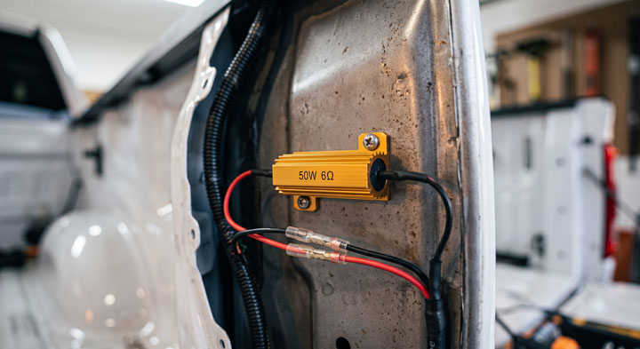
Mount a 50W 6-Ohm aluminum gold load resistor directly to metal bed sheet metal using self-tapping screws.
Never mount load resistors directly onto plastic bed caps or wiring looms, as resistors dissipate heat during operation.
Splice one lead of the load resistor to the positive turn signal wire and the opposite lead to the ground wire.
When you complete an f150 tail light wiring modification with parallel load resistors, current draw normalizes and stops dashboard error codes.
Step 5: Upgrading License Plate Tag Lights and Rear Auxiliary Harnesses
Reach behind the center rear bumper step pad to locate the twist-lock license plate lamp sockets.
Rotate the bulb socket ninety degrees counterclockwise and pull it out from the chrome bumper housing.
Pull the original glass wedge bulb straight out from the plastic socket connector.
Clean the interior socket contacts using electrical contact cleaner spray to remove road road salt buildup.
Insert your new LED license plate bulb firmly into the socket base.
If the LED fails to illuminate when running lights are turned on, remove the bulb, rotate it 180 degrees, and re-insert it.
Many LED wedge bulbs are polarity-sensitive and require positive and negative pins to align with specific socket contacts.
Re-insert the socket into the bumper housing and twist clockwise until the plastic tab locks securely in place.
Step 6: Weatherproofing Electrical Splices and Reassembling Light Housings
Protect all newly spliced wire taps, resistor leads, and butt connectors against moisture penetration.
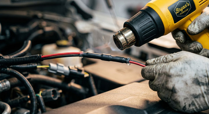
Slide heat shrink tubing over all exposed crimp terminals and apply heat with a heat gun until sealant oozes slightly from the ends.
Apply a thin coating of non-conductive dielectric grease inside all multi-pin light socket connectors.
Dielectric grease repels water drops, prevents metallic oxidation, and stops signal flickering caused by moisture condensation.
Snap the tail light assembly back into the rear bed fender alignment grommets.
Re-thread the two 8mm mounting bolts into the inner bed wall and tighten them securely by hand.
Avoid over-tightening these mounting bolts, as excess torque can crack plastic housing tabs easily.
Test all lighting functions including running lights, hazard flashers, brake pedal engagement, and reverse lamps with your helper.
Mastering these basic electrical tracing techniques empowers you to troubleshoot lighting faults with confidence.
Our mechanical team at Bryan’s Garage recommends inspecting your rear wiring connections before every long road trip or trailering journey.
Decoding Ford F150 Wire Color Codes Across Generations
Navigating factory wire colors on Ford trucks requires knowing your specific vehicle generation.
Ford updated rear chassis wiring schematics, connector shapes, and circuit trace colors across different production years.
Using an incorrect color schematic leads to miswired signal lines, blown fuses, or malfunctioning trailer brake feeds.
| F-150 Generation Years | Driver Side Turn / Stop Circuit | Passenger Side Turn / Stop Circuit | Running / Parking Light Circuit | Reverse Lamp Circuit | Chassis Ground Wire |
|---|---|---|---|---|---|
| 10th Gen (1997 – 2003) | Light Green / Orange | Dark Blue / Orange | Brown | Black / Pink | Solid Black |
| 11th Gen (2004 – 2008) | Light Green / White | White / Yellow | Brown | Black / Pink | Solid Black |
| 12th Gen (2009 – 2014) | Gray / Brown | Violet / Orange | Blue / Gray | Blue / White | Black / Violet |
| 13th Gen (2015 – 2020) | Gray / Brown | Green / Orange | Blue / Gray | Green / Brown | Black / Yellow |
| 14th Gen (2021 – 2024+) | Gray / Violet | Green / Blue | Blue / White | White / Green | Black / Gray |
11th and 12th Generation Circuit Characteristics
The 11th and 12th generation F-150 trucks rely on traditional mechanical relays and thermal flasher units combined with simple fuse panels.
On these models, checking for blown fuses under the passenger kick panel or engine compartment power box resolves dead rear light issues ninety percent of the time.
The running light circuit relies heavily on the main brown wire running along the driver side frame rail.
If both left and right running lights die simultaneously, inspect the frame rail harness connector near the spare tire crossmember.
13th and 14th Generation Microprocessor Controlled Systems
Starting with the 2015 aluminum body models, Ford introduced advanced solid-state Field Effect Transistor (FET) protection inside the Body Control Module.
These modern trucks no longer use traditional glass or mini fuses for individual rear light channels.
Instead, the BCM monitors real-time electrical current draw on every individual wire lead.
If the module detects a short circuit or over-current event, it shuts down power to that wire channel electronically.
Analyzing a modern ford f150 rear light wiring diagram reveals how the BCM acts as both electronic switch and automatic circuit breaker.