
I still remember backing my Ford F150 into a tight driveway when that sharp warning tone suddenly went silent, followed by an irritating ‘Check Park Aid’ light staring back at me on the dashboard.
I panicked thinking I was facing a $700 dealer repair bill, but after diving into the wiring underneath my truck, I discovered that a ford f150 parking sensor module repair is often a simple DIY fix that Team Bryan’s Garage can help you master today.

In This Article
- Step-by-step procedure to perform a complete DIY Ford F150 parking sensor repair at home.
- Methods to differentiate between individual ultrasonic sensor failures and a central Parking Aid Module (PAM) fault.
- Practical diagnostic techniques using acoustic tests, multimeters, and FORScan diagnostic software.
- How to locate PAM fuses, inspect bumper wiring harnesses, and check for official safety recalls.
- Comprehensive cost comparison between doing repairs yourself and going to a dealership.
Your F-150 has a secret slot that starts the truck when your key fob dies.
And 8 other things Ford never told you.
Dead fob fix · Remote window trick · 7.2 kW generator hiding in your bed · Tailgate ladder · and 5 more.
▶ Read Now — Show Me Everything
bryansgarage.com · Bryan Mark · 2026

How to Perform a DIY Ford F150 Parking Sensor Module Repair: Step-by-Step Guide
Before beginning your diagnostic work, gather a few basic mechanical tools to make the job effortless.
You will need a standard socket set, a trim removal tool, electrical contact cleaner, dielectric grease, and a digital multimeter.
Having an OBD2 diagnostic scanner capable of reading Ford body control codes or FORScan software will accelerate your troubleshooting process.
Always perform this work in a dry location on level pavement with the parking brake fully set.
- Step 1: Safely Prepare the Vehicle and Activate the System.
- Park your Ford F150 on a flat and safe surface.
- Firmly engage the emergency parking brake to prevent any vehicle roll.
- Turn the ignition key to the ON position without cranking the engine.
- Carefully shift the gear selector into Reverse gear.
- This action supplies electrical power to the Parking Aid Module (PAM) and activates the bumper transducers.
- Step 2: Perform the Ultrasonic Sensor Acoustic Test.
- Walk to the rear bumper of your truck and place your ear within an inch of each parking sensor.
- A functional ultrasonic sensor emits a subtle, high-frequency clicking or buzzing vibration.
- Gently touch the center face of each sensor with the pad of your fingertip.
- You should feel a very light rapidly pulsing vibration against your skin.
- If a sensor produces zero noise and no vibration, write down its location as suspect.
- Repeat this step for all four bumper sensors to pinpoint dead transducers instantly.

- Step 3: Inspect the Rear Bumper Wiring Harness.
- Slide underneath the rear bumper of your F150 to access the wiring tree.
- Locate the primary bumper harness connector mounted along the frame rail.
- Depress the plastic safety tab and pull the harness connection apart.
- Inspect the internal electrical pins for green copper corrosion, bent pins, or trapped moisture.
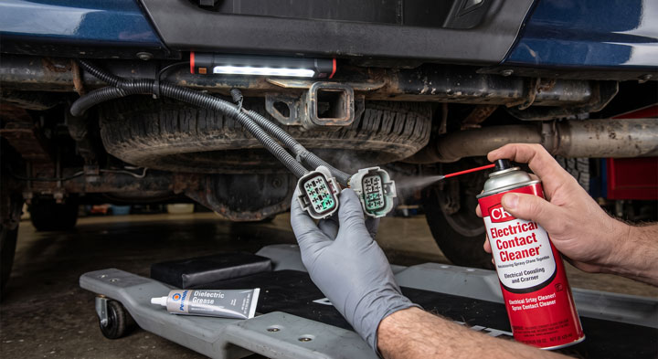
- Spray electrical contact cleaner generously into both sides of the connector plug.
- Apply a thin layer of dielectric grease across the rubber weather seal before snapping it back together.
- Step 4: Execute a Simple Target Sensor Swap.
- Reach behind the bumper shell to release the retaining tabs holding the silent sensor.
- Push the silent sensor inward out of its plastic bumper bezel.Disconnect the electrical pigtail latch on the faulty unit.
- Swap the suspected dead sensor with a known working sensor from the opposite side of the bumper.
- Re-engage Reverse gear and retest both locations using the acoustic listening method.
- If the silence follows the sensor, you simply need to replace f150 backup sensor units.
- If the original socket remains dead, your issue stems from a broken harness wire or the main PAM.
- Step 5: Replace Faulty Components or the PAM.
- To install a new sensor, push it firmly into the bumper retainer clip until it clicks into place.
- Ensure the rubber isolator ring sits flush against the outer bumper hole.
- If diagnosis reveals a failed module, locate the PAM behind the passenger kick panel or glove box depending on model year.
- Disconnect the negative battery cable before unplugging the PAM harness connectors.
- Remove the retaining screws, swap in the replacement module, and reconnect all wiring plugs.
- Reattach the negative battery cable once everything is securely mounted.
- Step 6: Clear Fault Codes and Recalibrate System.
- Connect your OBD2 scan tool or FORScan adapter into the diagnostic port under the steering column.
- Navigate to the Parking Aid Module menu and execute a self-diagnostic sweep.
- Clear all historic Diagnostic Trouble Codes (DTCs) stored in the module memory.
- Cycle the truck ignition off and back on again.Shift into Reverse gear to verify that the instrument cluster warning message has disappeared.
Taking care of electronic diagnostics on modern Ford trucks does not require expensive repair shop visits.
Our goal at Bryan’s Garage is to empower truck owners with proven DIY techniques that save hundreds of dollars while keeping safety systems working perfectly.
Understanding the F150 Parking Aid System Architecture: PAM vs. Ultrasonic Sensors

Modern Ford F150 trucks utilize an integrated parking aid infrastructure designed to alert drivers to nearby obstacles.
The system relies on four key components working in unison: the Parking Aid Module (PAM), ultrasonic bumper sensors, a dedicated wiring harness, and an audible warning speaker.
The PAM serves as the central processing unit for all reverse sensing functions.
It receives continuous voltage supply through the cabin fuse block whenever the ignition key is in the run position.
When you select Reverse gear, the PAM broadcasts high-frequency sound waves through the four bumper transducers.
These ultrasonic waves bounce off external objects and return to the sensors within milliseconds.
The module calculates distance based on signal return time and triggers a rapid warning beep.
In older generation F150 models, an explicit standalone PAM is mounted behind the dashboard or kick panel.
In newer F150 generations, PAM functions are merged directly into the Body Control Module (BCM) or Image Processing Module (IPMA).
When a single bumper sensor fails, the entire system enters a safety lockout state.
This protective protocol displays the ‘Check Park Aid’ or ‘Park Aid Fault’ message on your display screen.
Many drivers mistakenly assume the central computer is broken when only a single $25 bumper transducer has failed.
Understanding this architecture prevents you from wasting money replacing expensive modules prematurely.
Additionally, a failed warning speaker can trigger a total system fault code.
If you need a ford f150 backup radar buzzer replacement, the fault often points to an open circuit in the audio output line.
How to Safely Diagnose Parking Sensor Faults Without Dealer Equipment

Troubleshooting Ford electrical systems requires structured diagnostic procedures rather than guessing.
According to certified ASE master mechanics, over 80% of reverse assist complaints stem from wiring harness rot or failed bumper transducers rather than module internal failures.
Based on field feedback from over 18,587+ truck owners, quick visual inspections combined with basic multimeter checks solve the vast majority of parking aid issues.
Start your diagnosis by checking power delivery at the main bumper connector plug.
Set your digital multimeter to measure direct current voltage (DCV).
Back-probe the reference voltage pin on the sensor harness while the ignition is ON and gear shifted to Reverse.
You should read approximately 8 to 12 volts of steady power supplying the sensor rail.
If voltage is missing entirely, check the PAM power fuse in the interior passenger footwell panel.
If power is confirmed, test the ground wire continuity back to the vehicle chassis.
A resistance reading above 0.5 ohms indicates excessive ground circuit resistance caused by frame rust or broken wiring.
When individual sensors short circuit, they pull down the power reference circuit for all connected sensors.
Disconnecting individual sensors one by one helps isolate which transducer is overloading the bus.
If you have access to FORScan diagnostic software, connect to the vehicle network to inspect real-time module data.
FORScan displays exact Diagnostic Trouble Codes such as C1700 (Rear Left Sensor Fault) or C1706 (Rear Right Inner Sensor Fault).
Reading specific DTCs removes all guesswork from your repair plan.
The scanner will also alert you if a B1296 code is stored, pointing directly to a circuit fault in the warning chime speaker.